Bolting on an FMIC is one of those modifications that looks straightforward on paper but carries real consequences when the decision is made for the wrong reasons. A front-mount intercooler is not a guaranteed power gain, and fitting one before your setup actually demands it can introduce throttle lag, pressure drop, and packaging headaches without returning anything measurable in exchange.
This guide is built around a single premise: an FMIC upgrade is a consequence of other modifications, not a starting point. Once boost pressure climbs, power targets push beyond what your existing intercooler can handle, and heat soak becomes a consistent problem rather than an occasional one, the conversation about going front-mount becomes worth having. Until then, it probably is not.
What follows covers the physics of intercooler function, the specific conditions that make a stock or top-mount unit a genuine restriction, how to size a core correctly for your power target, and where piping length and mounting position can quietly erase the gains you were chasing. If you are running forced induction at an intermediate level and want to make this decision with actual data behind it, start here.
What Is an FMIC and Why It Is Not Always the Right Move
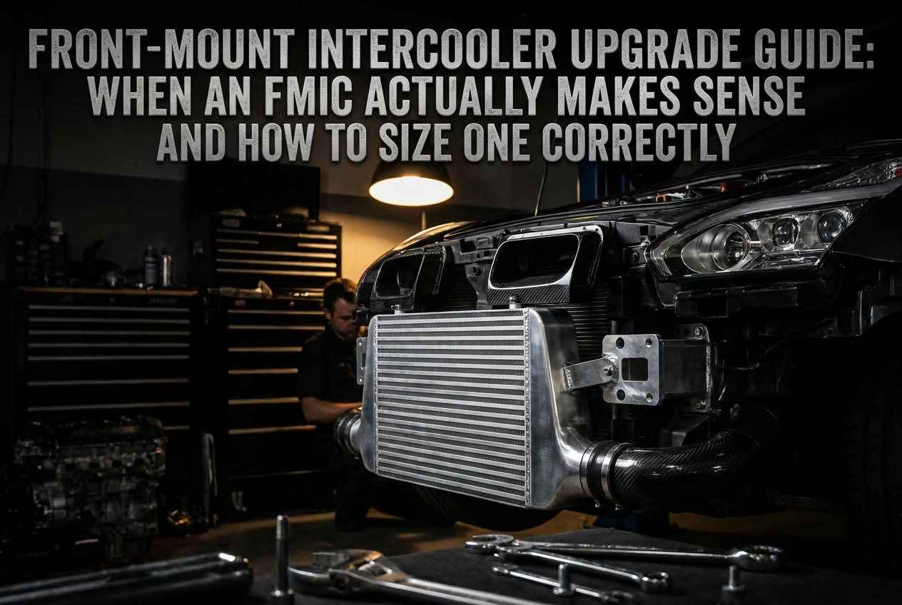
A front-mount intercooler (FMIC) is a charge air cooler mounted at the front of the vehicle, positioned ahead of the radiator where it receives direct, unobstructed airflow. A top-mount intercooler (TMIC) sits above the engine, typically fed by a bonnet scoop, whilst side-mount variants occupy the front corners of the engine bay. The key distinction is not just location but heat rejection capacity: an FMIC benefits from the highest volume of cool, dense ambient air and sits away from engine heat sources, giving it a structural advantage over both alternatives at sustained high power.
The core function of any intercooler is to reduce the temperature of compressed charge air before it enters the intake manifold. When a turbocharger compresses air, its temperature rises sharply. Cooler charge air is denser, carries more oxygen per unit volume, and critically, lowers the risk of detonation, allowing the ECU to run more aggressive ignition timing. Lower intake air temperatures (IATs) directly translate to more timing advance and better combustion efficiency.
The common mistake is treating an FMIC as a universal performance upgrade. On a stock or mildly modified turbo setup, the OEM intercooler is engineered to handle the thermal load of that power level. Fitting a front-mount to a car that has not outgrown its factory unit adds cost and piping complexity without delivering measurable gains. It can even introduce turbo lag if the core is oversized for the application.
The following sections work through the specific conditions, sizing methodology, and supporting modifications that determine whether your build has genuinely reached that point.
How Intercoolers Actually Work: The Physics You Need to Know
To understand why intercooler selection matters, you need to understand what happens to air the moment a turbocharger compresses it.
Adiabatic heating is the mechanism at the root of it. Compressing air raises its temperature sharply as a direct physical consequence. At modest boost levels with a healthy compressor, charge air temperatures typically rise 70–130°C above ambient. At higher pressures or with a worn compressor, that figure climbs further: measured data on a 1.0 bar / 60% efficiency system shows charge air arriving at the intercooler inlet around 60–70°C above ambient, and the figure climbs steeply as boost or compressor inefficiency increases. Hot charge air is less dense, carries less oxygen per cubic centimetre, and forces the ECU to retard ignition timing to avoid detonation. The intercooler’s sole job is to extract that heat before the charge reaches the intake manifold.
Three variables define how well any intercooler does that job:
- Thermal efficiency is the percentage of heat rejected relative to the maximum theoretically possible. For example, a core rated at 80% efficiency with 90°C of heat to reject would theoretically deliver charge air ~72°C cooler than the compressor outlet, though actual performance depends on airflow and core condition.
- Pressure drop is the boost pressure lost across the core. Well-engineered cores keep this below 0.014 bar (0.2 psi); poorly sized or excessively thick cores can consume significantly more.
- Flow capacity is the volume of air the core handles before it becomes a restriction. Exceed it and pressure drop rises sharply regardless of thermal performance.
Undersized cores saturate thermally under sustained load. The aluminium mass absorbs heat faster than airflow can dissipate it, and inlet air temperatures rise progressively across successive hard pulls. This IAT creep is particularly damaging on track, where back-to-back laps deny the core any recovery time.
Oversized cores carry a different penalty. Excess volume reduces charge velocity through the fins, raises pressure drop, and expands the volume the turbo must pressurise before boost builds, producing measurably slower spool-up and worse throttle response.
The goal is not the largest core available. It is the core that rejects sufficient heat for the target power level, maintains acceptable pressure drop, and matches airflow capacity to the engine’s actual output without adding unnecessary volume the turbo must overcome.
When Does Your Current Intercooler Actually Become a Restriction
Knowing the physics of thermal saturation is useful; knowing when your specific setup has actually crossed that threshold is what drives the decision.
Three logged signals indicate a restriction. First, sustained IATs noticeably elevated above ambient under load, a pattern confirmed by multiple back-to-back data logs rather than a single pull, suggest the core can no longer reject heat at the rate the engine is generating it. Second, ECU data showing ignition timing retard during sustained boost confirms the engine management is reacting to that heat by pulling timing to prevent detonation. Third, a power curve that flattens or falls on back-to-back runs, where the first pull is noticeably stronger than the third, points to progressive thermal saturation rather than a one-off anomaly.
OEM intercoolers are designed to a defined envelope. Manufacturers engineer the stock core to handle the boost pressure and fuelling the car leaves the factory with, plus a reasonable margin. Once a remap raises boost and fuelling beyond that envelope, heat rejection capacity is overwhelmed. The core was never sized for the load you are now putting through it.
Boost pressure is a useful reference point. As a general practitioner rule of thumb, not a hard engineering threshold, OEM intercoolers often remain adequate around 0.8 bar on a sensible tune, and thermal saturation becomes an increasingly likely issue as boost climbs beyond 1.2 bar alongside fuelling upgrades. Log your own data to confirm.
As established, TMIC positioning above the engine accelerates heat soak in slow traffic, the FMIC’s primary structural advantage.
Log the data before committing to hardware. A well-sized intercooler upgrade on a sensibly mapped engine can outperform an oversized FMIC fitted with long, poorly routed pipework. The intercooler is only the restriction if your logs confirm it is.
The Prerequisite Modifications That Should Come Before an FMIC
Once you have confirmed that your current intercooler is genuinely heat-saturating under load, the next question is not which FMIC to buy; it is whether the supporting modifications are in place to make one worthwhile.
ECU remapping or standalone engine management is the most critical prerequisite. A stock calibration contains timing and fuelling maps written around the thermal limitations of the OEM setup. Fitting a larger intercooler without a supporting remap means the ECU cannot advance ignition timing to exploit the cooler charge air; the stock map remains the hard ceiling on what the engine can produce. The intercooler improves conditions that the engine management is not calibrated to use. For a broader look at how intercooler upgrades fit into a sequenced build, see Why Upgrade Your Intercooler?
Turbocharger condition and efficiency must be verified before the intercooler is blamed for poor thermal performance. A worn or inefficient turbo compressor operates away from its efficiency island, producing charge air that is disproportionately hot relative to the boost pressure achieved. No intercooler compensates fully for a turbo generating excessive heat at the outlet; the correct step is to inspect the compressor map, check shaft play, and confirm the turbo is healthy before concluding the intercooler is the weak link.
Fuel system capacity sets the safe boundary for any power gain. Cooler charge air increases the engine’s tolerance for additional fuelling and timing advance, but only if the injectors and fuel pump can actually deliver the required volume. Upgraded charge cooling without matching fuel delivery creates a headroom the fuelling system cannot exploit without running lean.
Exhaust flow restriction can mask intercooler gains entirely. A restrictive downpipe or cat-back section limits how efficiently combustion gases exit the cylinder, constraining power independently of intake conditions. Sorting exhaust flow first isolates the variables and ensures any IAT improvement translates to measurable wheel power.
The FMIC belongs after this group because each prerequisite either raises the power ceiling that justifies it or equips the engine management to act on the thermal headroom it provides.
FMIC vs Top-Mount vs Water Spray: Choosing the Right Cooling Solution
With prerequisites sorted, the next decision is which cooling solution fits your build, because an FMIC is not automatically the correct answer.
FMIC vs TMIC: The Four Variables That Matter
| Variable | FMIC | TMIC |
|---|---|---|
| Heat rejection at high power | Stronger | Saturates sooner |
| Heat soak resistance | Better (away from engine) | Worse (sits above hot engine) |
| Pressure drop | Comparable if piping is efficient | Lower risk on short runs |
| Turbo response | Slight lag penalty | Faster on low-inertia setups |
The TMIC’s response advantage is real but modest. Logged data on 2-litre platforms suggests the additional piping volume of a typical FMIC conversion adds roughly 0.2 seconds to spool time, which is mappable via engine management and largely imperceptible in normal driving. As established, TMIC positioning above the engine accelerates heat soak in slow traffic, the FMIC’s primary structural advantage.
Water Spray and Water-Methanol Injection
Water spray, directing water or a water-methanol mix onto the TMIC core externally, is a legitimate cost-bridge solution for builds approaching the TMIC’s thermal limit without significantly exceeding it. It reduces IATs during a pull without the piping complexity of a full FMIC conversion.
Water-methanol injection is a related but distinct option. Injecting the mix pre- or post-intercooler reduces IATs and suppresses detonation risk simultaneously. The trade-offs are system complexity, a failure mode that can be catastrophic if fluid runs dry, and ongoing fluid cost.
Which Solution Wins in Which Scenario
- TMIC: Street builds at moderate boost, within OEM power envelope
- Water spray: Builds nudging the TMIC threshold; cost-effective before committing to a full conversion
- FMIC: High power targets, track duty cycles, or boost well beyond OEM parameters
Cost Context
An FMIC conversion is not just the core. Piping, BOV relocation, potential bumper modification, and a supporting retune all stack onto the core price. Water spray and water-methanol systems sit at a fraction of that total. If your build sits near the TMIC limit rather than past it, explore lower-cost options first. For broader context on where intercooler upgrades sit within a full build, this guide to the 10 performance upgrades that genuinely transform a car provides useful sequencing guidance.
How to Size an FMIC Correctly for Your Power Target
Once you have committed to an FMIC, the next decision is how to size it correctly. Getting this wrong in either direction costs performance.
Core volume is the primary variable. Core volume is calculated as height × width × thickness, expressed in cubic centimetres or litres. That figure determines how much heat the core can reject before thermal saturation occurs. The target volume must be matched to the airflow demand of the engine at its intended power level, not to the largest core that physically fits.
A practical sizing reference point: a 2.0-litre engine in that power bracket typically requires a meaningfully larger core than OEM, manufacturers’ fitment guides and dyno-validated sizing charts are the safest reference for your specific platform. Pushing beyond 400 bhp demands proportionally larger core volume, though bumper structure and radiator clearance frequently limit what is achievable in practice. Work within those constraints rather than forcing an oversized core that compromises fitment or radiator airflow.
Core thickness involves a genuine trade-off. Thicker cores offer higher heat rejection but raise pressure drop and reduce charge velocity; thinner cores preserve flow and response but saturate faster under sustained load. For most road-biased builds, a mid-range thickness balances both, consult the manufacturer’s pressure-drop specifications for the specific core.
Bar-and-plate versus tube-and-fin construction matters as much as dimensions. Bar-and-plate cores are widely favoured for modified and motorsport use on the basis of reported durability at elevated pressures; tube-and-fin cores are lighter and suit lower heat-load applications, verify with the manufacturer’s stated pressure and power ratings for the specific product.
Avoid the oversizing trap. A core significantly larger than the engine’s airflow demand reduces charge velocity, raises pressure drop, and slows turbo spool. The intercooler then introduces lag rather than eliminating it. Size to your actual power target, not to the maximum space available.
Piping diameter and routing interact directly with core sizing; those considerations are covered in the next section. If you are also reviewing supporting modifications, the Exhaust Pipes for Performance Cars: The Complete Buying Guide addresses how pipe diameter and flow capacity affect the overall power equation.
Piping Length, Routing, and Pressure Drop: Where FMIC Gains Can Be Lost
A correctly sized core delivers nothing if the pipework undoes its work. The performance case for an FMIC assumes the entire charge path is efficient; long, poorly routed pipework with multiple tight bends can introduce enough pressure drop to negate the thermal gains, particularly on smaller-displacement engines where boost pressure margins are tighter.
Every additional metre of charge pipe increases the volume the turbo must pressurise before boost reaches the engine and adds thermal mass that slows charge cooling. Tight bends compound this: each generates turbulence and a localised pressure loss. On a 1.8 or 2.0-litre platform running moderate boost, an extra metre of pipe plus several poorly executed bends can blunt throttle response and reduce peak charge pressure at the manifold.
Routing principles to follow:
- Keep total pipe length as short as the layout permits
- Mandrel bending is generally preferred to preserve the full internal diameter through bends; crush-bent pipe can reduce bore at each bend, introducing a restriction, check the supplier’s bend specification before purchasing
- Avoid consecutive tight bends in the same plane; stagger routing changes to allow flow to reattach between bends
- Specify smooth-bore aluminium or stainless internally; rough internal surfaces thicken the boundary layer and increase frictional losses at high flow rates
Diameter selection requires the same balance as core sizing. Undersized pipe raises pressure drop at high power. Oversized pipe reduces charge velocity, promotes turbulence at lower flow rates, and can cause condensation in cool UK conditions. The correct starting point is the turbo’s compressor outlet diameter; scale up only if your power target demands greater mass flow than that diameter supports.
BOV relocation is often overlooked during an FMIC conversion. The extended charge pipe volume means the standard BOV position may no longer vent the system quickly enough on throttle lift, raising the risk of compressor surge. Reposition the BOV as close to the throttle body as the post-intercooler pipework allows, and verify its flow rating is sufficient to evacuate the increased pipe volume within the turbo’s surge threshold.
Piping efficiency is closely linked to underbonnet organisation. If you are reviewing exhaust routing as part of the same build, this exhaust components buyer’s guide covers how downpipe and cat-back choices affect heat distribution in the engine bay, which directly influences how much heat your charge pipework is exposed to.
Mounting Position and Engine Bay Fitment: What Restricts Your Options
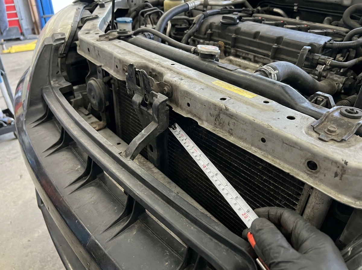
Even well-routed pipework cannot compensate for a core that physically cannot fit the available space. The default position for most FMIC kits places the core directly in front of the radiator, within the front bumper aperture. How much space that leaves depends entirely on bumper structure, crash box geometry, and how far forward the radiator sits on your specific platform. These dimensions vary significantly between models; assuming a core will fit based on another owner’s experience with a different car is a reliable way to waste money on a return shipment.
Radiator airflow is the thermal trade-off that most builders underestimate. A large core occupying the full bumper opening restricts ambient air reaching the radiator behind it. On a cool motorway run this rarely matters, but in slow traffic, on a hot day, or during back-to-back track laps, coolant temperatures will climb faster than before the conversion. On high-power builds, an uprated radiator or more effective electric fan setup is a worthwhile addition rather than an afterthought.
Post-intercooler piping proximity to heat sources is a separate problem. The turbo hot-side housing, exhaust manifold, and downpipe all radiate substantial heat into the engine bay. Cold-side pipework routed close to any of these will absorb heat before the charge air reaches the intake manifold, partially undoing the intercooler’s work. Heat-wrap on the pipework or shielding between the pipe run and the heat source addresses this directly. If you are reviewing the full engine bay layout, the Exhaust Replacement Guide: OEM vs Performance Upgrades for UK Drivers covers downpipe and exhaust considerations in detail.
MOT compliance is a hard constraint for UK road cars. Per the UK MOT inspection manual, section 6, bumper mounting integrity and crash structure condition are assessed at every inspection. Modifying or removing a crash box to fit a deeper core risks a structural failure. Research your specific model before committing to a core size.
Mock-fitting the core before purchase removes most of this risk. Where that is not practical, using a supplier with a vehicle-specific fitment list is the next best option. performancecarsparts.co.uk lists FMIC kits by vehicle application, reducing the chance of purchasing a core that cannot be installed without structural compromise.
UK-Specific Considerations: Ambient Temperature, MOT, and Road Use
The UK’s temperate climate is a genuine variable in intercooler decisions, not just background context. Average ambient air temperatures across most of the UK sit between 7°C and 18°C for the majority of the year, with summer peaks rarely sustaining above 20–25°C outside of brief heatwaves. That compressed thermal differential between ambient and compressed charge air means intercoolers work with a meaningful natural advantage here compared to hotter climates where sustained summer ambients can significantly exceed UK norms.
For road-only builds, this has a direct sizing implication. A core that would saturate thermally on a circuit in extreme heat may deliver excellent efficiency on a British B-road. Sizing to your actual duty cycle rather than worst-case global conditions is a legitimate approach for a street-focused UK build. That said, if you attend track days, that logic inverts entirely.
Track days represent the hardest thermal duty cycle your intercooler will face. Back-to-back laps remove the cooling intervals that road driving naturally provides. Heat soak accumulates across sessions, and IATs that look acceptable during a single hard pull can climb significantly over a 20-minute stint. A build intended for occasional circuit use must be sized for sustained thermal load, not the intermittent demands of road driving. UK venues such as Silverstone and Brands Hatch are not forgiving of undersized cooling in this respect.
On MOT and road legality, any modification that alters the front bumper mounting, crash structure, or radiator support sits in regulatory territory that extends beyond fitment. Visible front-end changes may attract scrutiny at MOT inspection, particularly where pedestrian safety structure compliance is affected. If your FMIC installation requires structural modification, an engineering assessment to confirm road legality is advisable before presenting the vehicle.
Insurance disclosure is not optional. An FMIC conversion is a material modification under UK insurance policy terms. Failing to declare it can invalidate your policy entirely in the event of a claim. This applies with particular force to track-day cars running on standard road policies, where the modification risk profile is already elevated.
Decision Framework: Do You Actually Need an FMIC
With the UK-specific context established, the final question is direct: does your specific build actually need an FMIC?
Work through this checklist before committing:
- Have you logged IATs under load? Sustained IATs noticeably elevated above ambient under load, a pattern confirmed by multiple back-to-back data logs rather than a single pull, indicate genuine thermal restriction.
- Does your ECU data show timing pull under boost? Timing retraction logged on back-to-back runs confirms the engine is protecting itself from heat-induced detonation risk.
- Is the rest of the build sorted? See the prerequisites section for the correct modification sequence.
- Does your power target exceed what a top-mount or water spray solution can handle? If you are not yet at that ceiling, cheaper interventions remain valid.
- Are you prepared for the full conversion? Piping, BOV relocation, and potentially radiator cooling are part of the package, not afterthoughts.
If the answer to points 1 and 2 is no, stop. Acceptable IATs and stable timing mean the existing intercooler is not the limiting factor. Core size is irrelevant if there is no thermal problem to solve.
Builds where an FMIC is clearly justified
- Stage 2 and above setups running elevated boost well beyond OEM parameters
- Track-focused cars completing back-to-back laps, where heat soak is logged and confirmed
- Builds where power targets have clearly outgrown the TMIC’s documented or tested capacity, verify with platform-specific data logs
- Any build where repeated hard pulls show measurable IAT rise and associated power drop
Builds where an FMIC is premature
- Lightly mapped cars still on the stock turbo
- Builds where ECU work or fuelling upgrades have not been completed
- Setups where the available budget would deliver more gain through prerequisite modifications first
The FMIC is a consequence of a build that has outgrown its existing cooling capacity. Deploy it when the data confirms the need, sized correctly for the power target, with the supporting modifications already in place.
Key Takeaways Before You Upgrade to an FMIC
If the decision framework confirmed your build genuinely needs an FMIC, keep these principles fixed before you commit budget.
An FMIC only returns measurable gains when the existing intercooler is a confirmed thermal restriction. Elevated IATs under load and logged timing pull are the evidence required. Without that data, the upgrade is speculative and the money is better directed elsewhere.
Sizing governs whether the conversion works or introduces new problems. Match core volume to your power target and duty cycle, a 2.0-litre engine in that power bracket typically requires a meaningfully larger core than OEM. See the sizing section for platform-specific guidance.
Prerequisite modifications are not optional context. The ECU remap, fuelling capacity, and turbo health must be addressed in the correct sequence before an FMIC can return its full benefit. See the prerequisites section for the correct modification sequence.
For vehicle-specific FMIC kits and force induction components, the range at performancecarsparts.co.uk is organised by vehicle application, reducing fitment risk. If you have questions about core sizing, piping compatibility, or which kit suits your build specification, the team is available via email or WhatsApp to support fitment and sizing queries directly.
Deploy the upgrade when the data justifies it, sized correctly, with the supporting modifications already in place.